Technical Specification and Installation guide: Conventional Reflective Beam Detector
• Product Overview & Core Benefits
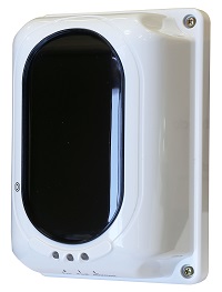
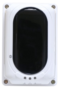
The Conventional Reflective Beam Detector is a single-ended, reflective infrared beam smoke detector equipped with a built-in microprocessor for high stability and robust environmental adaptability.
Global Compliance: Certified by LPCB and CE-CPR under EN 54-12:2002 standards.
Hassle-Free Alignment: Built-in digital nixie tube display and laser beam pointer minimize installation and alignment time.
Cost-Effective Design: Uses a single-ended design with a reflective mirror, eliminating wire-routing to both ends.
Smart Signal Compensation: Automatically adjusts for signal-weakening factors such as dust, slight shifting, and transmitter aging.
Self-Diagnosis: Monitors internal components automatically and reports system faults instantly.
• Key Specifications : Electrical & Interface Limits
Supply Voltage: 20V to 28V DC.
Power Usage: 23mA standby, 56mA commissioning, 33mA alarm state.
Interfacing Relays: Separate Fire and Fault relays rated at 2.0 A / 30 VDC (Normally Open).
Optics & Calibration
Operational Range: Adjustable via encoder from 8 to 100 meters across 4 distinct spans.
Directional Tolerance: Strict alignment angle of ± 0.4°.
Sensitivity Programing: Three user-selectable settings (2.6 dB, 3.8 dB, or 5.8 dB).
Environmental Protection
Temperature Range: Suitable for climates from -10°C up to 55°C.
Humidity Limit: Max 95% RH, non-condensing atmosphere.
Ingress Rating: IP30 default; upgrades to IP66 with an applied glue seal.
• Pre-Installation Requirements
Personnel: Must be installed by qualified or factory-trained personnel.
Location: Clean, dry, free from vibration, direct sunlight, glass walls, or reflective barriers.
Mounting Height:
Ceiling height below 8m: Install 0.5m to 1m below the ceiling.
Ceiling height above 8m: Install a minimum of 0.5m below the ceiling.
• Mounting Procedures
Fix Mounting Bracket: Mark holes using the bracket, drill, insert plugs, and secure it to the wall with four ST4x30 screws.
Mount Detector Base: Fix the detector base onto the bracket using two M4x12x10 screws.
Mount Reflective Mirror: Fix on the opposite wall using ST4x30 screws based on the distance:
8m – 40m range: Install 1 mirror.
40m – 100m range: Install 4 mirrors.
Cabling & Wiring (Max Cable Size: 1.5mm²).
D1 (+) & D2 (-): Connect to 24VDC Power Supply.
S1 & S2: Connect to handheld programmer for setup, or connect to D1 and D2 respectively during normal monitoring.
HJ1 & HJ2: Fire signal relay output (Normally Open).
GZ1 & GZ2: Fault signal relay output (Normally Close).
• Sensitivity and Span Programming
Configure the parameter settings before commissioning using either the internal DIP Switch (SW2) or a handheld programmer.
Set the correct Span (Distance) matching your actual field measurement:
Span 1 (8–20m) / Span 2 (20–40m) / Span 3 (40–70m) / Span 4 (70–100m).
• Alignment & Commissioning
Enter Commissioning Mode: Remove the cover, power on, and place the magnetic tool next to the Reed Switch until the Green LED turns on/blinks, then remove the tool.
Sightline Alignment: The built-in Laser Pointer turns on automatically. Loosen the M4x12 screw and adjust the horizontal/vertical wheels until the laser mark is at the center of the mirror.
Signal Adjustment: Monitor the digital display (ranges 1 to 8) while turning the wheels. Aim to reach 8 for an acceptable adjustment (2 or 3 is acceptable for long paths) until the Green LED stays steady on.
Finalize: Tighten the M4x12 screw and reinstall the detector cover.
Exit Commissioning: Place the magnetic tool next to the "(D)" mark on the cover. Remove it right after the Green LED turns off to enter normal monitoring mode.
• Frequently Asked Questions & Troubleshooting (FAQ)
Q1: Why is the Yellow LED constantly illuminated?
A: This indicates a System Fault. It usually means the light beam path is completely blocked, the transmitter/receiver lens is heavily covered in dust, or the device has drifted out of its alignment angle (± 0.4°). Clear any physical obstructions and clean the optical window.
Q2: How do I know if I need 1 or 4 mirror reflectors for my installation?
A: It is entirely dependent on your installation path distance. If the distance between the detector and the opposite wall is between 8 and 40 meters, use 1 reflector. If the distance is between 40 and 100 meters, you must install all 4 reflectors in a clustered grid.
Q3: Does this detector require manual cleaning adjustments due to dust build-up?
A: No. The device features an Automatic Compensation function. It automatically adjusts its software thresholds to compensate for gradual signal loss caused by dust contamination and transmitter aging. However, heavy blockages will still trigger a fault.
Q4: Can this detector be installed in outdoor environments with the roof?
A: Yes, but only with proper modification. Out of the box, it is rated at IP30 for indoor applications. To install it permanently or in areas exposed to moisture, you must apply a glue seal to upgrade its rating to IP66.
Q5: How do I reset the device after a fire alarm or fault signal has been cleared?
A: Perform a power cut for at least 2 seconds. The reset time of the device requires a brief power interruption (< 2 seconds) to clear latched relay states and re-initialize monitoring.
If you require this manual exported to an external schema spreadsheet, localized with targeted localized error codes, or want assistance creating compliance documentation, please let me know!